2. Input file format
This section explains the input format and provides examples for basic usecases. Furthermore a variety of template files can be found in io/Templates. If the input xsd scheme was subject to change, this documentation needs to be updated.
<roadNetwork xmlns:xsi="http://www.w3.org/2001/XMLSchema-instance" xsi:noNamespaceSchemaLocation="../xml/input.xsd">
    <segments>
        ...
    </segments>
    <links refId="1" hdgOffset="0.0" xOffset="0" yOffset="0">
        ...
    </links>
    <closeRoads>
        ...
    </closeRoads>
</roadNetwork>
2.1. Segments
The segments node stores information about each physical road in the network as it’s child nodes. Each segment represents a seperate road, roundabout or junction. The different types segments are outlined below.
2.1.1. ConnectingRoad
A connecting Road is used to represent a single street. Two types (i.e ‘access’ and ‘main’) of roads can be used to select different presets for the road’s characteristics.
2.1.1.1. Road
Name |
Type |
Range |
Description |
Required |
id |
int |
positive |
id of the road inside of the segment |
yes |
classification |
string |
‘main’ ‘access’ |
set the road to main or access road |
yes |
2.1.1.2. LineType
At the moment three different types of line are supported. Straight lines, curves and spirals.
Name |
Type |
Range |
Description |
Required |
length |
double |
positive |
length of the reference line in m |
yes |
R |
double |
positive |
constant radius of the arc |
yes |
Rs |
double |
positive |
starting radius of the spiral |
yes |
Re |
double |
positive |
ending radius of the spiral |
yes |
2.1.1.3. Key points
Connecting roads are used for simple streets that are linked once at each endpoint at most
The outermost ConnectingRoad element holds the ID in the segment namespace
The road element holds an ID that is relative to the ConnectingRoad’s ID. This is used to distinguish seperate parts of the same segment element
2.1.2. Junctions
Junctions are a key component that are used connect multiple roads. ‘access’ and ‘main’ roads are behaving differently when used in a junction. While ‘main’ roads are ‘cut’ appart to create an intersection, ‘access’ roads are ‘appended’ to the intersection point. While the same junction can be represented by different junction types, it is adviced to stick to their intended usecases.
2.1.2.1. Junction
Name |
Type |
Range |
Description |
Required |
id |
int |
positive |
id of the road inside of the segment |
yes |
type |
string |
‘2M’ ‘MA’ ‘M2A’ ‘3A’ |
type of junction |
yes |
2.1.2.2. AutomaticWidening
Name |
Type |
Range |
Description |
Required |
active |
string |
‘none’ ‘all’ ‘main’ ‘access’ |
specify where automatic widening is applied |
yes |
length |
double |
positive |
length of the additional lane |
no |
double |
double |
positive |
length of the transitioning part |
no |
2.1.2.3. IntersectionPoint
The intersection point stores information about the location and geometry about the point in which all roads meet. The reference road dictates the position of the junction.
Name |
Type |
Range |
Description |
Required |
refRoad |
int |
positive |
id of the reference road of the junction |
yes |
s |
string |
positive |
position of the junction in road direction |
yes |
2.1.2.4. RoadLink
In most cases manual road links can be omitted. If the user wants to create custom road linkage they can use the road link tag.
Name |
Type |
Range |
Description |
Required |
fromId |
int |
positive |
id of the fromRoad |
yes |
toId |
int |
positive |
id of the toRoad |
yes |
fromPos |
string |
‘start’ ‘end’ |
position of the fromRoad link |
yes |
toPos |
string |
‘start’ ‘end’ |
position of the toRoad link |
yes |
2.1.2.5. laneLink
If the user wants to create elaborate junctions they might want to manually link each lane. However, in most cases this is not necessary.
Name |
Type |
Range |
Description |
Required |
fromId |
int |
positive |
id of the fromLane |
yes |
toId |
int |
positive |
id of the toLane |
yes |
left |
string |
‘solid’ ‘broken’ ‘none’ |
lane marking on the left side |
no |
right |
string |
‘solid’ ‘broken’ ‘none’ |
lane marking on the right side |
no |
2.1.2.6. Key points
Junctions need to be linked to the starting point of each adjacent road
A junction must be used if more than two roads are linked to each other
The intersection points of access roads need to be linked at their start or end positions
Similar to the connecting road namespace, the junction ID is in the segment ID namespace and the road IDs are relative to the segment ID
2.1.2.7. Examples
M2A Junction
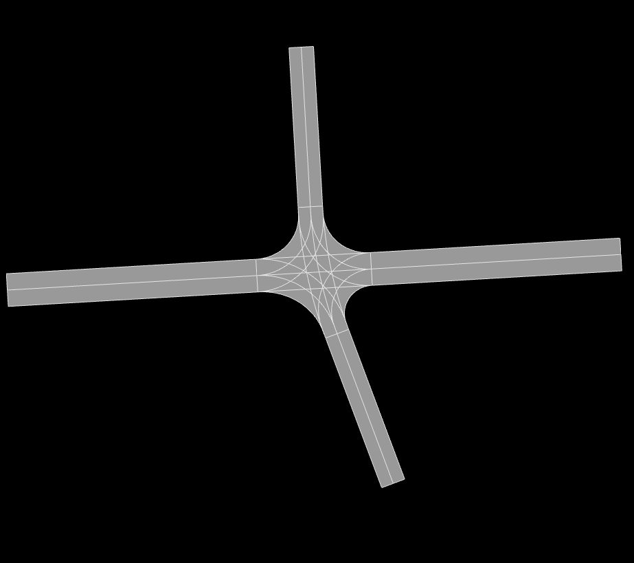
<roadNetwork xmlns:xsi="http://www.w3.org/2001/XMLSchema-instance" xsi:noNamespaceSchemaLocation="../xml/input.xsd">
   <segments>
        <junction id="1" type="M2A">
        <road id="1" classification="main" >
            <referenceLine>
                <line length="150"/>
            </referenceLine>
        </road>
        <road id="2" classification="access" >
            <referenceLine>
                <line length="150"/>
            </referenceLine>
        </road>
        <road id="3" classification="access" >
            <referenceLine>
                <line length="150"/>
            </referenceLine>
        </road>
        <intersectionPoint refRoad="1" s="75">
            <adRoad id="2" s="20" angle="-1.27"/>
            <adRoad id="3" s="20" angle="1.57"/>
        </intersectionPoint>
        <coupler>
            <junctionArea gap="10">
                <roadGap id="2" gap="15"/>
                <roadGap id="3" gap="15"/>
            </junctionArea>
        </coupler>
    </junction>
    </segments>
</roadNetwork>
3A Junction
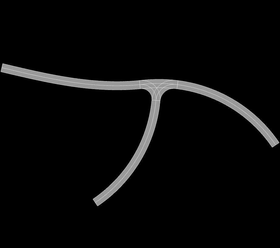
<roadNetwork xmlns:xsi="http://www.w3.org/2001/XMLSchema-instance" xsi:noNamespaceSchemaLocation="../xml/input.xsd">
   <segments>
    <junction id="1" type="3A">
        <road id="1" classification="access" >
            <referenceLine>
                <spiral length="100"  Rs="-150" Re="0"/>
            </referenceLine>
        </road>
        <road id="2" classification="access" >
            <referenceLine>
                <arc length="100"  R="-100"/>
            </referenceLine>
        </road>
        <road id="3" classification="access" >
            <referenceLine>
                <arc length="100"  R="-100"/>
            </referenceLine>
        </road>
        <intersectionPoint refRoad="1" s="100">
            <adRoad id="2" s="0" angle="3.14"/>
            <adRoad id="3" s="0" angle="1.57079632679"/>
        </intersectionPoint>
        <coupler>
            <junctionArea gap="10">
                <roadGap id="2" gap="15"/>
            </junctionArea>
            <connection type="all"/>
        </coupler>
    </junction>
    </segments>
</roadNetwork>
MA Junction
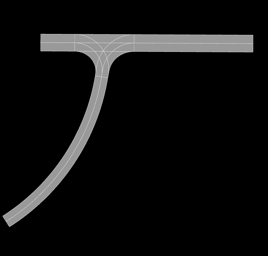
<roadNetwork xmlns:xsi="http://www.w3.org/2001/XMLSchema-instance" xsi:noNamespaceSchemaLocation="../xml/input.xsd">
   <segments>
    <junction id="1" type="MA">
        <road id="1" classification="main" >
            <referenceLine>
                <line length="400"/>
            </referenceLine>
        </road>
        <road id="2" classification="access" >
            <referenceLine>
                <arc length="100"  R="-100"/>
            </referenceLine>
        </road>
        <intersectionPoint refRoad="1" s="200">
            <adRoad id="2" s="0" angle="-1.57"/>
        </intersectionPoint>
        <coupler>
            <junctionArea gap="10">
                <roadGap id="2" gap="15"/>
            </junctionArea>
        </coupler>
    </junction>
    </segments>
</roadNetwork>
2M Junction
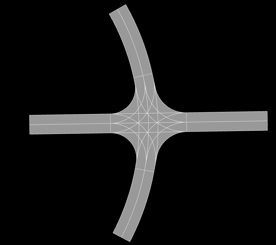
<roadNetwork xmlns:xsi="http://www.w3.org/2001/XMLSchema-instance" xsi:noNamespaceSchemaLocation="../xml/input.xsd">
   <segments>
    <junction id="1" type="2M">
            <road id="1" classification="main" >
                <referenceLine>
                    <line length="100"/>
                </referenceLine>
            </road>
            <road id="2" classification="main" >
                <referenceLine>
                    <arc length="100"  R="-100"/>
                </referenceLine>
            </road>
            <intersectionPoint refRoad="1" s="50">
                <adRoad id="2" s="50" angle="-1.57"/>
            </intersectionPoint>
            <coupler>
                <junctionArea gap="10">
                        <roadGap id="1" gap="15"/>
                    <roadGap id="2" gap="20"/>
                </junctionArea>
            </coupler>
        </junction>
    </segments>
</roadNetwork>
Additional Lane
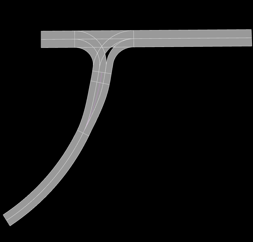
<roadNetwork xmlns:xsi="http://www.w3.org/2001/XMLSchema-instance" xsi:noNamespaceSchemaLocation="../xml/input.xsd">
   <segments>
        <junction id="1" type="MA">
            <road id="1" classification="main" >
                <referenceLine>
                    <line length="100"/>
                </referenceLine>
            </road>

            <road id="2" classification="access" >
                <referenceLine>
                    <arc length="100"  R="-100"/>
                </referenceLine>

            </road>
            <intersectionPoint refRoad="1" s="100">
                <adRoad id="2" s="0" angle="-1.57"/>
            </intersectionPoint>
            <coupler>
                <junctionArea gap="10">
                    <roadGap id="2" gap="15"/>
                </junctionArea>
                <connection type="all"/>
                <additionalLanes>
                    <additionalLane roadId="2" roadPos="end" type="left" length="5" />
                </additionalLanes>
            </coupler>
        </junction>
    </segments>
</roadNetwork>
Multiple Lanes
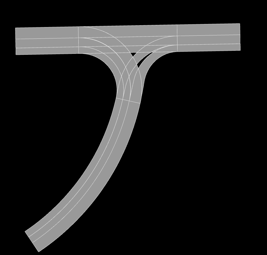
<roadNetwork xmlns:xsi="http://www.w3.org/2001/XMLSchema-instance" xsi:noNamespaceSchemaLocation="../xml/input.xsd">
   <segments>
        <junction id="1" type="MA">
            <road id="1" classification="main" >
                <referenceLine>
                    <line length="100"/>
                </referenceLine>
                <lanes>
                <lane id="2" type="driving" width="5">
                        <roadMark type="solid" color="white" width="0.1"/>
                </lane>
                <lane id="1" type="driving">
                        <roadMark type="solid" color="white" width="0.1"/>
                        </lane>
                    <lane id="0" type="driving"> </lane>
                        <lane id="-1" type="driving" width="3">
                            <roadMark type="solid" color="white" width="0.1"/>
                    </lane>
                </lanes>
            </road>

            <road id="2" classification="access" >
                <referenceLine>
                    <arc length="100"  R="-100"/>
                </referenceLine>
                <lanes>
                <lane id="2" type="driving" width="5">
                        <roadMark type="solid" color="white" width="0.1"/>
                </lane>
                <lane id="1" type="driving">
                        <roadMark type="solid" color="white" width="0.1"/>
                        </lane>
                    <lane id="0" type="driving"> </lane>
                        <lane id="-1" type="driving" width="3">
                            <roadMark type="solid" color="white" width="0.1"/>
                    </lane>
                </lanes>
            </road>
            <intersectionPoint refRoad="1" s="50">
                <adRoad id="2" s="0" angle="-1.57"/>
            </intersectionPoint>
            <coupler>
                <junctionArea gap="10">
                    <roadGap id="2" gap="15"/>
                </junctionArea>
                <connection type="all"/>

            </coupler>
        </junction>
    </segments>
</roadNetwork>
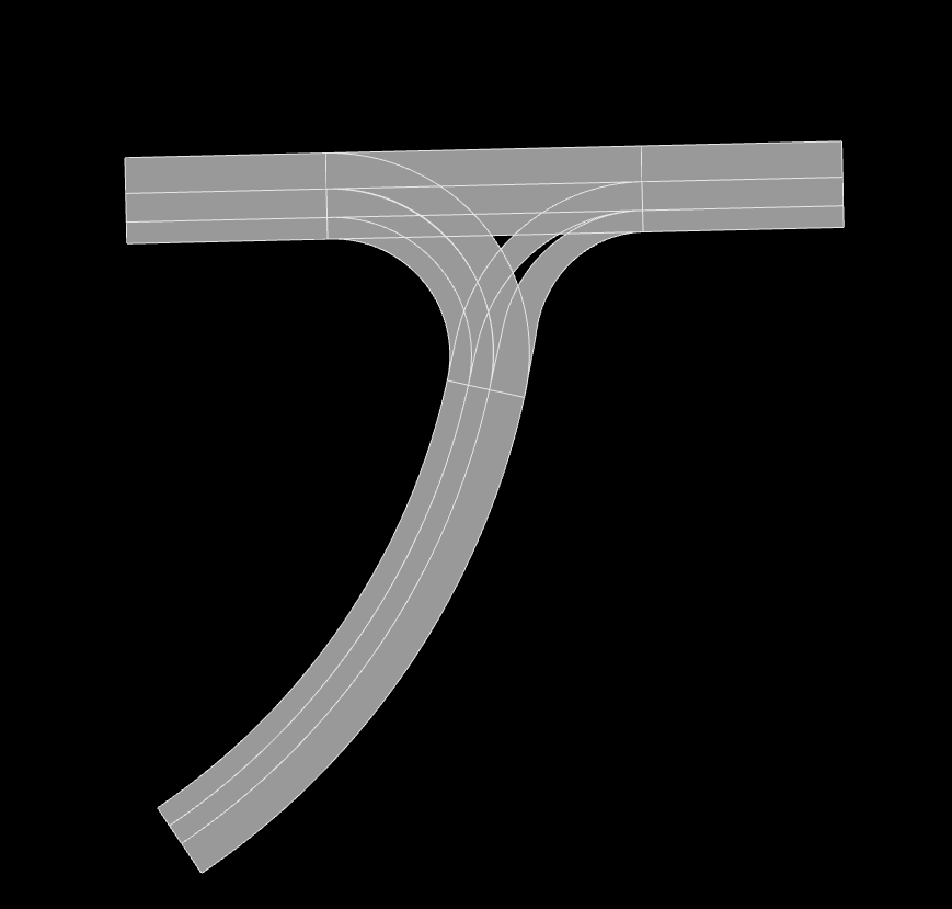
<roadNetwork xmlns:xsi="http://www.w3.org/2001/XMLSchema-instance" xsi:noNamespaceSchemaLocation="../xml/input.xsd">
    <segments>
        <junction id="1" type="2M">
            <road id="1" classification="main" >
                <referenceLine>
                    <line length="200"/>
                </referenceLine>
                <lanes>
                <lane id="2" type="driving" width="5">
                        <roadMark type="solid" color="white" width="0.1"/>
                </lane>
                <lane id="1" type="driving">
                        <roadMark type="solid" color="white" width="0.1"/>
                        </lane>
                    <lane id="0" type="driving"> </lane>
                        <lane id="-1" type="driving" width="3">
                            <roadMark type="solid" color="white" width="0.1"/>
                    </lane>
                </lanes>
            </road>

            <road id="2" classification="main" >
                <referenceLine>
                    <arc length="200"  R="-100"/>
                </referenceLine>
                <lanes>
                <lane id="2" type="driving" width="5">
                        <roadMark type="solid" color="white" width="0.1"/>
                </lane>
                <lane id="1" type="driving">
                        <roadMark type="solid" color="white" width="0.1"/>
                        </lane>
                    <lane id="0" type="driving"> </lane>
                        <lane id="-1" type="driving" width="3">
                            <roadMark type="solid" color="white" width="0.1"/>
                    </lane>
                </lanes>
            </road>
            <intersectionPoint refRoad="1" s="100">
                <adRoad id="2" s="100" angle="-1.57"/>
            </intersectionPoint>
            <coupler>
                <junctionArea gap="10">
                    <roadGap id="2" gap="15"/>
                </junctionArea>
                <connection type="all"/>

            </coupler>
        </junction>
    </segments>
</roadNetwork>
2.1.3. Roundabout
Represents a simple roundabout. While it is possible to manually create a roundabout by using junctions, it is tedious and requires a lot of redundant code. Therefore it is best practice to use the roundabout template instead. The tool will generate several junctions that belong to one junction group in the output.
2.1.3.1. Circle
Name |
Type |
Range |
Description |
Required |
id |
int |
positive |
id of the circle (usually 1) |
yes |
classification |
int |
‘main’ ‘access’ |
sets the circular road of the rb to access or main road |
yes |
2.1.3.2. Reference Line
Name |
Type |
Range |
Description |
Required |
length |
double |
positive |
length of the circular road in the roundabout |
yes |
2.1.3.3. Key points
Roundabouts need to be linked to the starting point of each adjacent road
Roundabouts will be represented by junctions in the open drive output
2.1.3.4. Example
<roundabout id="1">
    <circle id="1" classification="access" >
        <referenceLine>
            <circle length="320.5"/>
        </referenceLine>
        <lanes>
                <lane id="1" type="delete" />

                <lane id="-3" type="driving">
                    <roadMark   type="solid" color="white" width="0.13"/>
                </lane>
                <lane id="-2" type="driving">
                    <roadMark   type="broken" color="white" width="0.13"/>
                </lane>
                <lane id="-1" type="driving">
                    <roadMark   type="broken" color="white" width="0.13"/>
                </lane>
                <lane id="0" type="driving" />
        </lanes>
    </circle>

    <road id="2" classification="access" >
        <referenceLine>
                <line length="150"/>
        </referenceLine>
    </road>
    <road id="3" classification="access" >
        <referenceLine>
                <line length="100"/>
        </referenceLine>
    </road>
    <road id="4" classification="access" >
        <referenceLine>
                <line length="100"/>
        </referenceLine>
    </road>
    <road id="5" classification="access" >
        <referenceLine>
                <line length="100"/>
        </referenceLine>
    </road>

    <intersectionPoint refRoad="1" s="80">
        <adRoad id="2" s="20" angle="-1.56"/>
    </intersectionPoint>
    <intersectionPoint refRoad="1" s="160">
        <adRoad id="3" s="20" angle="-1.56"/>
    </intersectionPoint>
    <intersectionPoint refRoad="1" s="240">
        <adRoad id="4" s="20" angle="-1.56"/>
    </intersectionPoint>
    <intersectionPoint refRoad="1" s="320">
        <adRoad id="5" s="20" angle="-1.6"/>
    </intersectionPoint>
    <coupler>
        <junctionArea gap="20">
        </junctionArea>
    </coupler>
</roundabout>
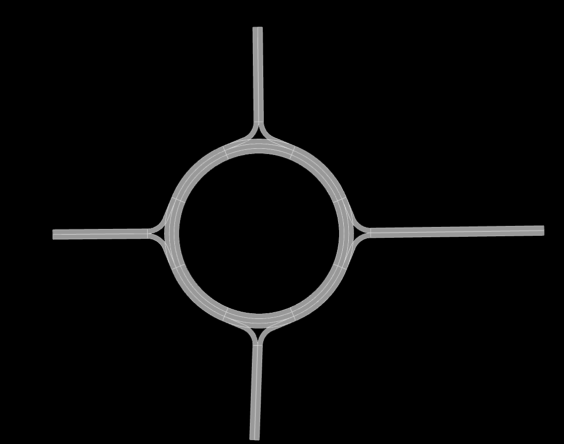
Generated with https://odrviewer.io/
2.2. Lanes
2.2.1. Lane
Name |
Type |
Range |
Description |
Required |
id |
int |
all |
id of the lane |
yes |
type |
string |
‘driving’ ‘restricted’ ‘none’ ‘delete’ |
type of the lane |
no |
width |
double |
positive |
width of the lane |
no |
speed |
double |
positive |
speed limit of the lane |
no |
Notes:
If no further lane information is provided a total of three default lanes will be generated. One in each direction and a dividing middle lane
If at least one lane is provided no default lanes will be generated
2.2.2. RoadMark
Name |
Type |
Range |
Description |
Required |
type |
int |
‘solid’ ‘broken’ ‘none’ |
specifies the roadmark |
no |
color |
string |
color |
color of the roadmark |
no |
width |
double |
positive |
roadmark width |
no |
Colors: ‘standard’, ‘blue’, ‘green’, ‘red’, ‘white’, ‘yellow’, ‘orange’.
2.2.3. LaneWidening and laneDrop
If the user wants to expand or shrink the road’s lane count during its course, they can use the lanewidening or lanedrop tag.
Name |
Type |
Range |
Description |
Required |
side |
int |
‘-1’ ‘1’ |
side of the lane that will be added/dropped |
yes |
s |
double |
positive |
starting position of the lane widening/drop |
yes |
length |
double |
positive |
length of the laneDrop |
no |
2.2.4. RestrictedArea
Name |
Type |
Range |
Description |
Required |
length |
double |
positive |
length of the restricted area of the lanewidening or lanedrop |
no |
Note: The length of the restricted area must be larger than the length of the lanewidening or the lanedrop. The starting position is inherited by the parent node.
2.2.5. Material
Name |
Type |
Range |
Description |
Required |
surface |
string |
surface material code depending on application |
no |
|
friction |
double |
positive |
friction coefficient |
no |
roughness |
double |
positive |
roughness coefficient |
no |
2.2.6. Key points
Lane ids are centered around 0 and store their location relative to the driving direction. Positive ids are to the left of the driving direction and negative ids are on the right.
Lanes from linked segments with the same ids are linked if not specified otherwise
Lane ids are not exclusive
2.2.7. Example
<lanes>
    <lane id="-2" type="driving">
        <roadMark   type="solid" color="white" width="0.13"/>
    </lane>
    <lane id="-1" type="driving">
        <roadMark   type="broken" color="white" width="0.13"/>
    </lane>
    <lane id="0" type="driving" />
    <lane id="1" type="driving">
        <roadMark   type="solid" color="white" width="0.13"/>
    </lane>
    <laneDrop side="-1" s="100" length="50" />
</lanes>
2.3. Linkage
The links element defines the reference segment, which will be used as a refernece point for all other roads. The user can provide an offset.
2.3.1. Links
Name |
Type |
Range |
Description |
Required |
refId |
int |
positive |
specifying the global reference segment |
yes |
xOffset |
int |
positive |
specifying a global x offset |
yes |
yOffset |
int |
positive |
specifying a global y offset |
yes |
hdgOffset |
int |
positive |
specifying a global angle offset |
yes |
All links between segments are stored in a segmentLink element. Each segment is linked at their endpoint or their startpoint. While most other links can be generated automatically by the tool, the user has to link every segment manually.
2.3.2. SegmentLink
Name |
Type |
Range |
Description |
Required |
fromSegment |
int |
positive |
id of the firstSegment that will be linked |
yes |
toSegment |
int |
positive |
id of the toSegment that will be linked |
yes |
fromRoad |
int |
positive |
id of the specific road in the fromSegment that will be linked |
yes |
toRoad |
int |
positive |
id of the specific road in the toSegment that will be linked |
yes |
fromPos |
string |
‘start’ ‘end’ |
specifies if the fromSegment should be linked at its beginning or end |
yes |
toPos |
string |
‘start’ ‘end’ |
specifies if the toSegment should be linked at its beginning or end |
yes |
2.3.2.1. Key points
Junctions and roundabouts need to be linked to the starting point of each adjacent road
Each segment must be linked to the biggest component. No other components can exist in the network.
Segments have a seperate namespace from Roads, i.e. multiple roads with the ID 1 can exist under differen segments
2.3.3. Example
<links refId="1" hdgOffset="0.0" xOffset="0" yOffset="0">
    <segmentLink fromSegment="1" toSegment="2" fromRoad="1" toRoad="1" fromPos="end" toPos="start" />
    <segmentLink fromSegment="2" toSegment="3" fromRoad="1" toRoad="2" fromPos="end" toPos="end" />
    <segmentLink fromSegment="3" toSegment="4" fromRoad="3" toRoad="1" fromPos="end" toPos="start" />
    <segmentLink fromSegment="3" toSegment="5" fromRoad="4" toRoad="1" fromPos="end" toPos="end" />
    <segmentLink fromSegment="6" toSegment="1" fromRoad="2" toRoad="1" fromPos="end" toPos="start" />
</links>
2.4. CloseRoads
To smoothly close open connections, roads and their respective linkage information can automatically be generated. The syntax of closing roads is identical to the road links.
Name |
Type |
Range |
Description |
Required |
fromSegment |
int |
positive |
id of the firstSegment that will be linked |
yes |
toSegment |
int |
positive |
id of the toSegment that will be linked |
yes |
fromRoad |
int |
positive |
id of the specific road in the fromSegment that will be linked |
yes |
toRoad |
int |
positive |
id of the specific road in the toSegment that will be linked |
yes |
fromPos |
string |
‘start’ ‘end’ |
specifies if the fromSegment should be linked at its beginning or end |
yes |
toPos |
string |
‘start’ ‘end’ |
specifies if the toSegment should be linked at its beginning or end |
yes |
2.4.1. Example
<closeRoads>
        <segmentLink fromSegment="1" toSegment="2" fromRoad="1" toRoad="1" fromPos="end" toPos="end" />
        <segmentLink fromSegment="3" toSegment="3" fromRoad="5" toRoad="4" fromPos="end" toPos="end" />
        <segmentLink fromSegment="6" toSegment="5" fromRoad="1" toRoad="1" fromPos="end" toPos="end" />
        <segmentLink fromSegment="7" toSegment="1" fromRoad="4" toRoad="1" fromPos="end" toPos="start" />
        <segmentLink fromSegment="7" toSegment="7" fromRoad="2" toRoad="3" fromPos="end" toPos="end" />
</closeRoads>